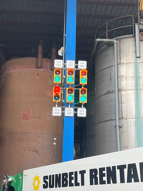
Agitator Motor Indication Lights
CE was contracted by a customer to provide true status indication lights for six critical agitator motors. This was a turnkey installation, meaning CE would provide all parts and smarts. There was limited room in the motor control center (MCC), so the first step was deciding the largest enclosure size that we could possibly fit on the wall. Once this was decided, I knew what size back plate I could use for assembling the necessary control devices.
The CT switch/transducer I was able to find monitors one phase of a three phase load, in this application being a motor. The switch part of the CT will directly control a relay. It was necessary to use a control relay for the additional, normally closed contact that would be used for the red indication light. Circuit analysis was a very helpful skill in creating the control drawings for this project, specifically the control of current in series and parallel circuits. Control diagram is provided here.
Part of this project was to plan for a future, larger project for this plant. This particular CT also provides a 4-20 ma output based off of the sensed current of the motor. This output will be wired up to a PLC at a later date to allow the plant to see how hard the motor is working.
One issue I encountered was due to an assumption I made. The enclosure was a square 30"x30" can. I assumed that the back plate would also be a square. This was not the case. One aspect of construction is the ability to adapt to changes. We were forced to drill out the hinge pins and rotate the door 90 degrees to allow for the proper back plate orientation.
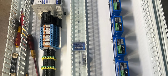
Back Plate Assembly

Device labelling for troubleshooting

Final layout before wiring devices.

Bench Tested
CE subscribes to the belief that you get what you inspect not what you expect. That being said, I had never used one of these CT's before. Once I had completed construction of the back plate, I felt the need to test to verify correct operation. I cut the plug off of a chop saw and ran the hot wire through a CT. I had a 4' LED fixture laying around that I wired up to a relay that that CT controlled. Using a suicide cable, i.e. a drop cord with the female plug cut off, I was able to provide the panel with 120v. After seeing the lamp burn the way I had intended, I was confident that the installation would be a success and that my customer would be satisfied with the install.
Here is the finished installation with indication lights installed. It needed to be plainly visible to the operators from a distance away.